Insights · Megaproject of the week · 14.09.2026
Electrify the liquefaction, and the governing fire moves into the electrical building
Papua LNG cleared its last contractual milestones before FID on 7 September, with EPC tendering closed and operatorship passing to ExxonMobil. The plant will drive its refrigerant compressors with electric motors instead of gas turbines — a decision that removes the classic LNG ignition source and puts a substation-sized fire load on the critical path instead.
Project data
What happened
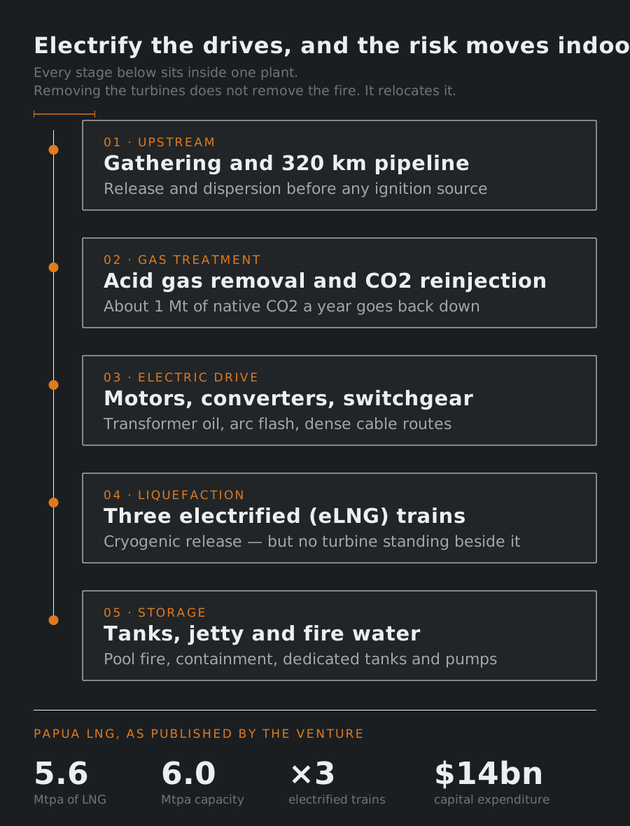
On 7 September TotalEnergies announced that Papua LNG has “achieved major contractual and commercial milestones, marking decisive steps towards a Final Investment Decision”. EPC tendering is closed, and operatorship passes to ExxonMobil, operator of the neighbouring PNG LNG, while TotalEnergies keeps 20% and its offtake share. Redesign and rebidding since 2024 have taken “close to US$ 4 billion” out of the estimate, bringing capital expenditure to “around US$ 14 billion” against “a total production of 5.6 Mtpa”.
The engineering line sits further down. The venture describes three new electrified — “eLNG” — trains at Caution Bay, taking total liquefaction capacity to 6 Mtpa including 2 Mtpa tolled through the existing PNG LNG trains, fed from the Elk and Antelope fields by a 320 km pipeline network, with one of eleven wells reinjecting about 1 Mt of native CO2 a year. The preferred EPC contractor puts it plainly: “electric motors — rather than conventional gas turbines — drive the refrigerant compressors.”
Analysis: the ignition sources leave, the load does not
Electrifying liquefaction is announced as a carbon decision. In fire engineering it is a redistribution: it moves the largest ignition sources out of the process area and concentrates an unfamiliar fire load in buildings that used to be secondary.
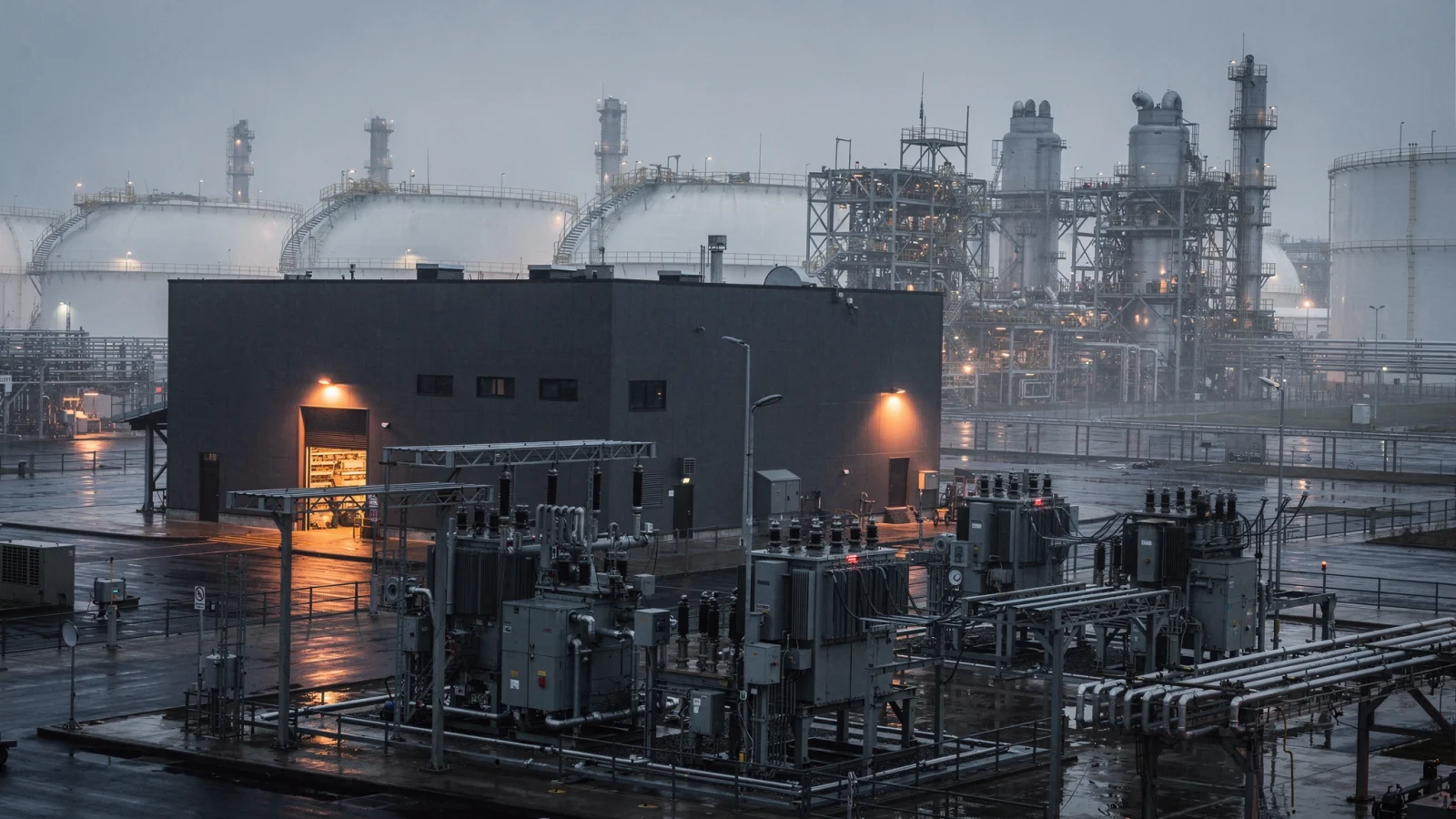
Taking out the gas turbines takes out half the classic scenario. A mechanical-drive train puts turbine exhausts, hot casings and large lubricating-oil inventories inside or beside a classified area, and much of the layout exists to keep a release and a hot surface apart. Electric drive breaks that pairing. What remains is the release without an ignition source conveniently next to it, which shifts the weight of the design onto dispersion rather than the jet fire — a different governing case, and a different argument to make to the insurer.
In exchange the plant acquires a substation-sized fire load on the critical path. Compression at this scale means high-voltage motors, converter and variable-speed drive rooms, converter transformers, switchgear halls, and several times the cable volume of a mechanical-drive plant. The scenarios are ordinary — transformer oil, arc flash, dense cable routes — and so are the answers. What is new is their position. Three trains behind one electrical backbone makes this a common-mode question: a fire in one electrical building can idle capacity well beyond the equipment it damages, and delivery times for large motors and HV switchgear are not measured in weeks.
The purge and the penetration are where two disciplines miss each other. Large machines next to a classified area raise protection-concept questions: pressurised enclosures, purge integrity, the action on loss of purge and who is authorised to take it. Penetrations between a safe-area electrical building and the process are at once a gas path and a fire path. Area classification to IEC 60079-10-1 and passive fire protection are usually drawn by different people, at different times.
Why this reaches European projects
Electrification of process drivers is the direction European projects are already being pushed. What differs is the frame it lands in: Seveso III where inventories justify it; ATEX in both of its directions — equipment, and the protection of workers — which is where very large electric machines and their enclosures sit; the Construction Products Regulation for what is built into the works, cable above all; the EN 1473 frame for onshore LNG installations; and an insurer who reads the electrical building as the single point of loss.
The published material says what drives the compressors. It does not say what generates the electricity — and that decides whether a power block with its own combustion, fuel gas and oil inventories stands inside the fence, in which case much of the hazard removed from the train is merely relocated a few hundred metres.
Before an electrified concept is frozen, the questions are narrow. Which single fire takes more than one train off line. Whether drive and converter rooms are separated by distance, by construction, or only by a door. How penetrations between the electrical buildings and the process are sealed against smoke and against gas. And what fire water duty the site must hold once the governing scenario is electrical rather than hydrocarbon.
Sources
- Papua New Guinea: TotalEnergies Takes Decisive Steps Towards Final Investment Decision on Papua LNG — TotalEnergies, 07.09.2026
- Project Overview — Papua LNG, 14.09.2026
- JGC-Hyundai Joint Venture Considered as EPC Contractor for a Major Low-Carbon LNG Plant Project in Papua New Guinea — JGC Holdings Corporation, 31.03.2026
- ExxonMobil to take operatorship of Papua LNG as $14 billion project nears FID — World Oil, 07.09.2026
Editorial rule, applied without exception: no figure, designation or claim of fact is published without verification against a primary source. Everything under “Analysis” is our engineering judgement, not reported fact. Illustrations are generated images, not photographs of the facilities described.